Automation-components ACI/Button Sensor Manuel d'utilisateur

Naviguer en ligne ou télécharger Manuel d'utilisateur pour Thermomètres Automation-components ACI/Button Sensor. Automation Components ACI/Button Sensor User Manual Manuel d'utilisatio

  • Télécharger
  • Ajouter à mon manuel
  • Imprimer
  • Page
    / 2
  • Table des matières
  • MARQUE LIVRES
  • Noté. / 5. Basé sur avis des utilisateurs
Vue de la page 0
Installation and Operation Instructions
ACI/Button Sensor
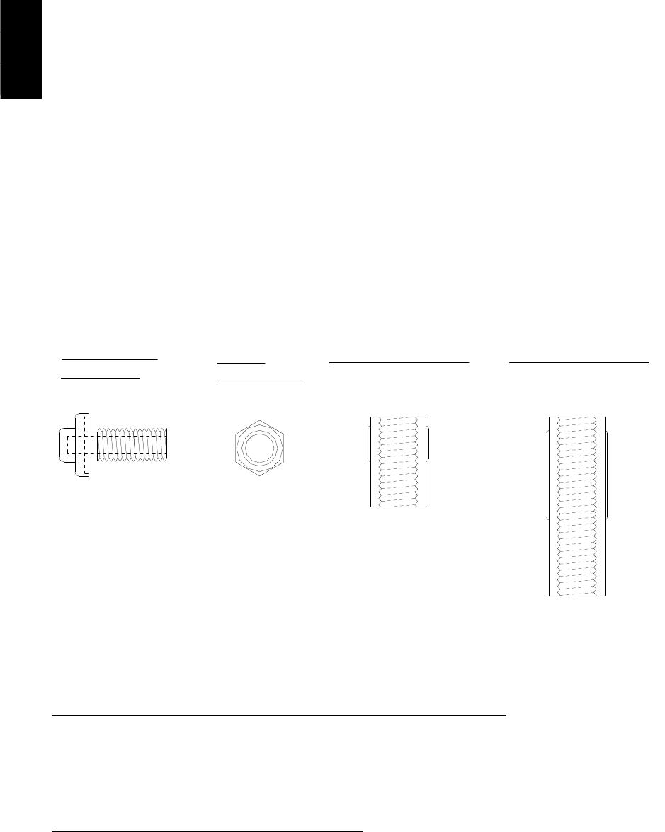
2305 Pleasant View Rd. Middleton Industrial Park Middleton, WI 53562
PH: (608) 831-2585 FAX: (608) 831-7407
I0000024.DOC Rev 4
Page 1 of 2
A
C
I
utomation
omponents
nc.
READ THESE INSTRUCTIONS BEFORE YOU BEGIN INSTALLATION
All ACI thermistors and RTD temperature sensors are both non-polarity and non-position sensitive. All thermistor and
RTD type sensors are included with (2) 22 AWG stranded etched Teflon wires for making all of the proper connections.
The universal mounting kit includes (1) 3/8-16” Hex Jam Nut, (1) 1” Delrin Spacer/Insulator, and (1) 2” Delrin
Spacer/Insulator.
TROUBLESHOOTING
Sensor reads 0 ohms or very low Sensor or wires are shorted together
Sensor reads infinity or very high Sensor or wires have been damage and are open
Erratic readings Bad wire connections - Condensation or Moisture problem
PART DESCRIPTIONS
Brass/Stainless
Steel Button
1" x .620 O.D. Spacer
3/8"-16
Hex Jam Nut
2" x .620 O.D. Spacer
MOUNTING INSTRUCTIONS
This unit is suitable for mounting in many different locations such as in a cabinet, control panel, walls, or in a standard
mounting plate. The spacers are to be used to insulate the brass or stainless steel threaded portion of the sensor from any
drafts or temperature changes in the wall as well as to mount the sensor into the wall.
Board or Panel Mounting using the 3/8” Hex Nut or 1” or 2” Delrin Spacer
1. First drill a 3/8” hole in the board or panel and insert the button sensor (2) wires through the hole and thread
the hex nut or 1” or 2” spacer onto the button sensor until tight. If the plate or panel is relatively thin, similar
to a one gang junction box cover be sure to use the 1” or 2” Delrin spacer depending on the thickness of the
box or enclosure. The Delrin spacer will insulate the sensor from any drafts inside the wall. A small piece of
foam or insulation may be inserted in the bottom of the Delrin spacer to better insulate the sensor if necessary.
Drywall Mounting using the 1” or 2” Delrin Spacer
1. First drill a 5/8” hole in the drywall. Next insert the button sensor (2) wires through the top of 1” or 2” Delrin
spacer. Now thread the 1” or 2” Delrin spacer onto the back of the button sensor. Now make all of the wire
connections using either crimp on connectors or wire nuts. A small piece of foam or insulation may be
inserted into the bottom of the 1” or 2”Delrin spacer to better insulate the sensor if necessary. Next insert the
button sensor assembly into the wall until it is flush to the wall as shown in Figure 1 below. You may need to
gently tap the button sensor assembly with a hammer for it to go into the drywall.
Vue de la page 0
1 2

Résumé du contenu

Page 1

Installation and Operation Instructions

Page 2 - 1/2" Conduit

2305 Pleasant View Rd.  Middleton Industrial Park  Middleton, WI 53562 PH: (608) 831-2585  FAX: (608) 831-7407 I0000024.DOC Rev 4 Page 2 of 2 WALL

Commentaires sur ces manuels

Pas de commentaire